
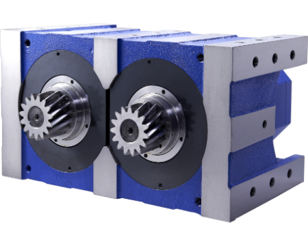
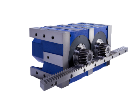
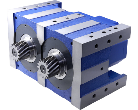
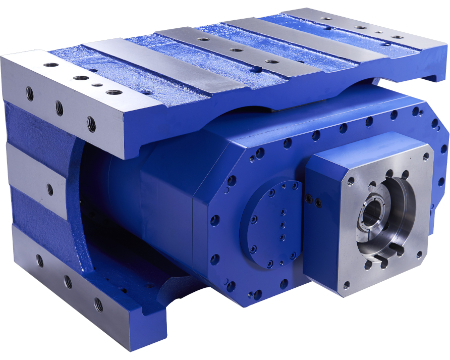
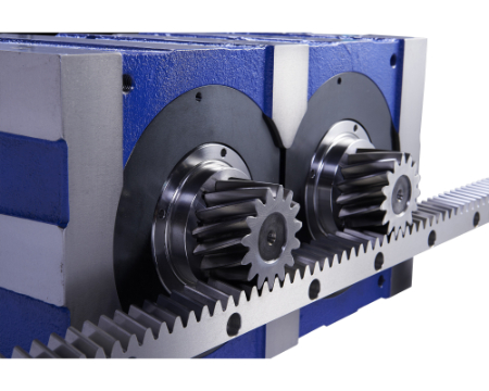
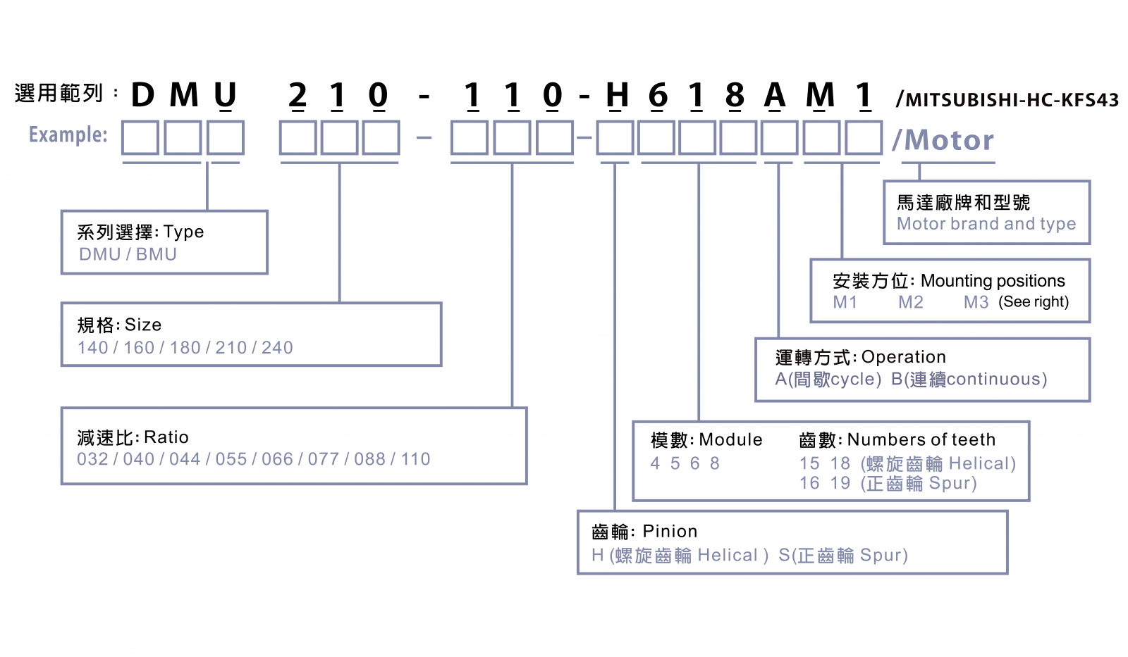
DMU (Box design) Mechanical Backlash-free
| Precision Level |
|
|---|---|
| Torsional Rigidity |
|
| Price Range |
|
- Industry Applications
- CNC Machine Tools
- Special Purpose Machines (SPMs)
- Engineering Machinery
- Specially designed machinery is able to eliminate clearance from the gearbox inner and from between pinions and racks. This completely supplements and clears up the backlash of manufacture or/and installation while gearboxes drive both pinions and racks.
- Mechanical preload system, driven by a single servo motor, can reach the goal of electrical preload system, save controller and driver cost.
- Backlash eliminating enables processing tool tracks stable, which prolongs tool life.
- Parameter setting can be easier for enclosed mechanical preload system, driven by a single servo motor, than electrical preload system.
- Backlash reducing enables improved processing surface smoothness and accuracy.
- For the well-designed structure and high duty material of taper roller bearing, the output shaft of the reducer can bear the huge axial and radial load, which could be wide application.
- One-piece output design, special high strength the fewer teeth of pinion and smaller servo motor, achieve the low moment of inertia.
- Precision gear grinding tooth surface smooth, precise tooth.
- For an excellent design, high accuracy and low moments of inertia.
- For the professional gear producing experience and the serious quality control of manufacturing processes.
- After a long time operation, the preloading force is still maintained.
This product does not have dimensions for 1-stage for reference. We recommend searching for dimensions for 2-stage instead.
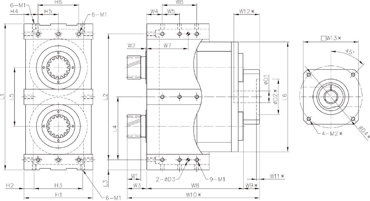
DMU dimensions (2-stage ratio 32 / 40 / 44 / 55 / 66 / 77 / 88 / 110)[mm]
| Frame size | DMU140 | DMU160 | DMU180 | DMU210 | DMU240 |
|---|---|---|---|---|---|
| stage | 2 | 2 | 2 | 2 | 2 |
| H1 | 220 | 270 | 320 | 380 | 420 |
| H2 | 32.5 | 35 | 35 | 50 | 60 |
| H3 | 155 | 200 | 250 | 280 | 300 |
| H4 | 45 | 60 | 70 | 100 | 90 |
| H5 | 65 | 75 | 90 | 90 | 120 |
| H6 | 130 | 150 | 180 | 180 | 24 |
| L1 | 470 | 530 | 600 | 720 | 815 |
| L2 | 405 | 460 | 530 | 620 | 695 |
| L3 | 32.5 | 35 | 35 | 50 | 60 |
| L4 | 202.5 | 230 | 265 | 310 | 347.5 |
| L5 | 189 | 207 | 240 | 270 | 320 |
| L6 | 353 | 386 | 458 | 512 | 600 |
| W1 | 43 | 43 | 54 | 65 | 88 |
| W2 | 3 | 6 | - | - | 4 |
| W3 | 62 | 64 | 68 | 86.5 | 115 |
| W4 | 50 | 60 | 80 | 90 | 90 |
| W5 | 55 | 65 | 75 | 105 | 95 |
| W6 | 110 | 130 | 150 | 210 | 180 |
| W7 | 132.5 | 157.5 | 192.5 | 247.5 | 232.5 |
| W8 | 309 | 336.5 | 385 | 480.5 | 519.5 |
| ※W9 | 51.5 | 52 | 61 | 56 | 48 |
| ※W10 | 422.5 | 452.5 | 514 | 623 | 682.5 |
| ※W11 | 10 | 15 | 15 | 10 | 10 |
| ※W12/td> | 82 | 82.5 | 98 | 85 | 83.5 |
| ※W13 | 176 | 176 | 176 | 176 | 190 |
| D1(F7) max. | 38 | 38 | 42 | 48 | 55 |
| ※D2 | 114.3 | 114.3 | 114.3 | 114.3 | 180 |
| D3 | 9.5 | 9.5 | 11.5 | 13.5 | 13.5 |
| ※D4 | 200 | 200 | 200 | 200 | 215 |
| M1 | M12*P1.75 | M16*P2 | M20*P2.5 | M20*P2.5 | M20*P2.5 |
| ※M12 | M12*P1.75 | M12*P1.75 | M12*P1.75 | M12*P1.75 | M12*P1.75 |
※Actual dimensions marked above may vary from different servo motors.
We persistently research in and develop our products, and we have made every effort to maintain the specification data above correct. If there is any discrepancy between the data and real dimensions, please refer to products or may contact us for updated data.
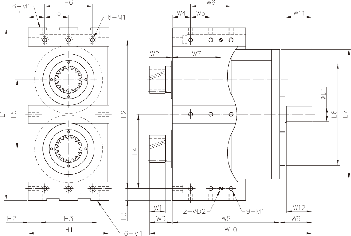
DMU dimensions(Input shaft type) (2-stage ratio 32 / 40 / 44 / 55 / 66 / 77 / 88 / 110)[mm]
| Frame size | DMU140 | DMU160 | DMU180 | DMU210 | DMU240 |
|---|---|---|---|---|---|
| Stage | 2 | 2 | 2 | 2 | 2 |
| H1 | 220 | 270 | 320 | 380 | 420 |
| H2 | 32.5 | 35 | 35 | 50 | 60 |
| H3 | 155 | 200 | 250 | 280 | 300 |
| H4 | 45 | 60 | 70 | 100 | 90 |
| H5 | 65 | 75 | 90 | 90 | 120 |
| H6 | 130 | 150 | 180 | 180 | 24 |
| L1 | 470 | 530 | 600 | 720 | 815 |
| L2 | 405 | 460 | 530 | 620 | 695 |
| L3 | 32.5 | 35 | 35 | 50 | 60 |
| L4 | 202.5 | 230 | 265 | 310 | 347.5 |
| L5 | 189 | 207 | 240 | 270 | 320 |
| L6 | 353 | 386 | 458 | 512 | 600 |
| W1 | 43 | 43 | 54 | 65 | 88 |
| W2 | 3 | 6 | - | - | 4 |
| W3 | 62 | 64 | 68 | 86.5 | 115 |
| W4 | 50 | 60 | 80 | 90 | 90 |
| W5 | 55 | 65 | 75 | 105 | 95 |
| W6 | 110 | 130 | 150 | 210 | 180 |
| W7 | 132.5 | 157.5 | 192.5 | 247.5 | 232.5 |
| W8 | 292.5 | 313 | 366 | 450.5 | 493.5 |
| W9 | 88 | 88 | 102 | 115 | 111 |
| W10 | 422.5 | 465 | 536 | 652 | 719.5 |
| W11 | 73 | 73 | 83 | 85 | 85 |
| W12 | 70 | 70 | 80 | 82 | 82 |
| D1(k6) max. | 40 | 40 | 42 | 50 | 55 |
| D2 | 9.5 | 9.5 | 11.5 | 13.5 | 13.5 |
| M1 | M12*P1.75 | M16*P2 | M20*P2.5 | M24*P3 | M30*P3.5 |
※Actual dimensions marked above may vary from different servo motors.
We persistently research in and develop our products, and we have made every effort to maintain the specification data above correct. If there is any discrepancy between the data and real dimensions, please refer to products or may contact us for updated data.
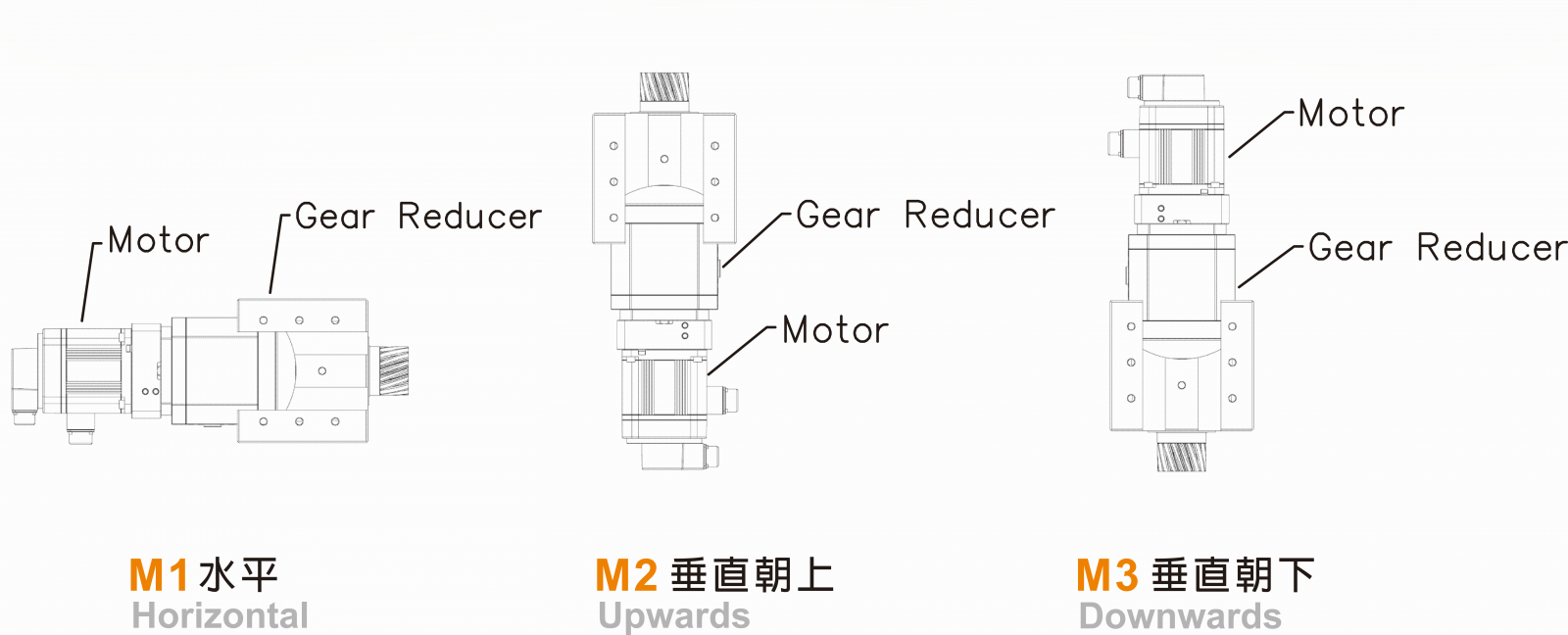
Mounting positions
.jpg)
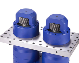
Rack
Related Products
BMU (Plate design) Mechanical Backlash-free
| Frame Sizes | 140-240 |
|---|---|
| Ratios | 2-stage: 32-110 |
| Torque Value | 1120-9395 |
| Backlash | - |